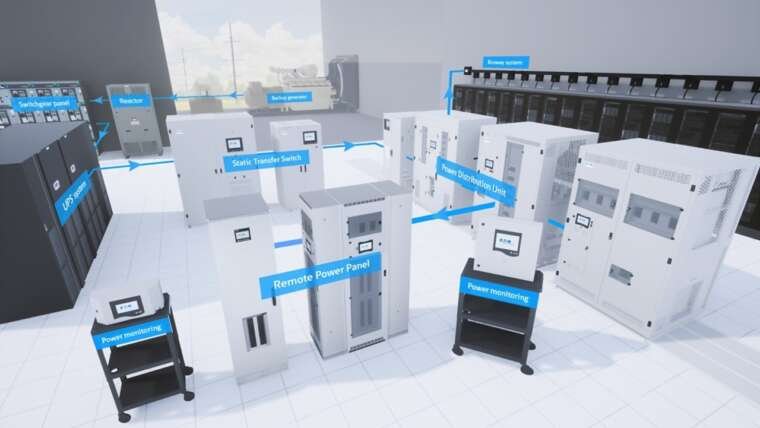

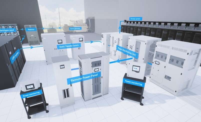

Maintaining power stability inside high-density data centers requires constant oversight of facility-wide power distribution networks. Sitting at the heart of server hall power delivery, a Floor PDU (Power Distribution Unit equipped with internal step-down transformers, primary input breakers, sub-feed panelboards, and intelligent monitoring) takes high-voltage bulk utility or UPS feeds and transforms them into clean 3-phase electricity. However, when electrical loads across the three individual phase lines (Phase A, Phase B, and Phase C) become uneven, a critical operational issue occurs: voltage imbalance.
Voltage imbalance occurs when the voltage magnitudes across the 3-phase supply lines are unequal, or when the phase angles between them deviate from their standard 120-degree spacing. In a busy server environment, even a small voltage imbalance—as little as 2% to 3%—can overheat internal transformer windings, cause neutral conductors to carry dangerous stray currents, trip upstream breakers unexpectedly, and shorten the operating lifespan of connected server power supply units (PSUs).
Understanding what causes voltage imbalances in floor distribution units empowers data center managers, MEP engineers, and facility technicians to identify root causes early, optimize phase loading, and safeguard facility uptime.
1. Understanding 3-Phase Power and Electrical Imbalance
To diagnose voltage imbalance in floor distribution units, it helps to understand how 3-phase power is delivered to modern server hardware.
In a balanced 3-phase electrical system, power is split across three distinct alternating current (AC) conductors. Each phase carries the exact same voltage magnitude, and each sine wave is separated evenly by 120 degrees in phase timing. When all three phases supply identical electrical loads, the vector sum of the current returning through the shared neutral line equals zero.
-
Balanced 3-Phase System: Phase A (100A), Phase B (100A), and Phase C (100A) result in a Neutral Return Current of 0 Amps, maintaining a clean and stable ground.
-
Unbalanced 3-Phase System: Phase A (160A), Phase B (80A), and Phase C (90A) generate a Neutral Return Current of 55+ Amps, creating excess heat and voltage sags across the network.
However, when one phase line carries significantly more current than the others, unequal voltage drops occur along the internal busbars, transformers, and distribution cables. This uneven voltage drop creates voltage imbalance across the system.
Defining Percentage of Voltage Imbalance
Under standards established by the National Electrical Manufacturers Association (NEMA) and IEEE, percent voltage unbalance is calculated by dividing the maximum deviation from the average voltage by the average voltage, then multiplying by 100.
For example, if your three line-to-line phase voltages measure 208V, 204V, and 196V, the average voltage is 202.6V. The maximum deviation from the average is 6.6V (202.6V minus 196V). This yields a voltage unbalance of 3.25%—a level high enough to trigger system warnings and cause equipment overheating.
2. Primary Causes of Voltage Imbalance in Floor PDU Systems
Voltage imbalance rarely occurs overnight. It usually develops gradually over months of server hardware installations, rack re-configurations, and uneven load distribution.
1. Uneven Single-Phase Server Load Distribution
While modern data halls supply 3-phase power directly to high-density cabinets, many individual IT devices (such as network switches, storage arrays, and single-corded 1U/2U servers) run on single-phase branch circuits.
When electricians or IT technicians repeatedly land new single-phase branch breakers on whichever panelboard space is easiest to reach—rather than tracking phase balance across Phase A-B, B-C, and C-A—one phase line becomes heavily loaded while the others remain underutilized. The oversubscribed phase line experiences a larger internal voltage drop, pulling its voltage down relative to the lightly loaded phases.
2. High Concentrations of Non-Linear IT Loads and Harmonics
Modern computing equipment utilizes switch-mode power supplies (SMPS) that draw current in rapid, non-linear pulses rather than smooth continuous sine waves.
These non-linear current pulses generate high levels of triplen harmonics (specifically the 3rd, 9th, and 15th harmonic orders). Triplen harmonics do not cancel each other out on the neutral line; instead, they add together constructively on the shared neutral conductor. This massive harmonic current flow alters the neutral-to-ground reference, causing voltage distortion and severe phase-to-neutral voltage imbalances.
3. Upstream Utility and Supply Voltage Asymmetry
Not all voltage imbalances originate inside the white space. The primary 480V 3-phase power arriving at your floor distribution unit from the facility’s main switchgear, utility transformer, or Uninterruptible Power Supply (UPS) may already carry incoming voltage asymmetry.
Unequal loading on utility distribution lines, single-phase utility capacitor bank switching, or asymmetrical transformer windings upstream will pass voltage imbalances directly down to your floor-standing distribution units.
4. High-Resistance Electrical Connections and Busbar Degradation
Continuous high-amperage draw combined with thermal expansion and contraction can cause physical electrical connections inside power distribution equipment to degrade over time. Loose busbar bolts, corroded cable lugs, or pitted internal breaker contacts create high-resistance points along a single phase path.
Under heavy load, this elevated resistance causes a localized voltage drop across that specific phase line, creating a measurable voltage imbalance at the output panelboard.
3. Operational Risks and Consequences of Unbalanced Voltage
Allowing a floor distribution unit to operate with unmanaged voltage imbalance introduces severe electrical, thermal, and financial risks to your data center.
Consequences of Voltage Imbalance
-
Transformer Overheating and Insulation Breakdown: Unequal phase currents create asymmetrical magnetic flux inside the PDU’s step-down isolation transformer. This causes local hot spots in the primary and secondary copper windings, accelerating thermal insulation breakdown and risking premature transformer failure.
-
Overloaded Neutral Conductors: In an unbalanced 3-phase system, current no longer cancels out on the neutral line. The returning unbalanced current—combined with harmonic distortion—forces high amperage down the neutral conductor. This can overheat neutral busbars and cause insulation fires if neutral lines are not double-sized.
-
Nuisance Circuit Breaker Tripping: Asymmetrical phase loads mean one phase line approaches its 80% National Electrical Code (NEC) continuous limit while the other two phases operate far below capacity. The heavily loaded phase breaker may trip unexpectedly during peak processing workloads, taking operational server racks offline.
-
Reduced Efficiency in Server Power Supplies (PSUs): Dual-corded enterprise servers rely on balanced internal power supply units. Operating on unbalanced phase voltages forces one PSU to work harder and run hotter than its paired redundant PSU, accelerating component wear and lowering power supply efficiency.
4. How to Prevent, Monitor, and Correct Voltage Imbalance
Eliminating voltage imbalance requires a combination of real-time monitoring, intelligent branch circuit telemetry, proper initial load engineering, and preventive maintenance protocols.
-
Step 1: Audit Current Load Profiles: Measure active Amperage across Phase A, B, and C via DCIM telemetry to identify high-draw circuits.
-
Step 2: Rebalance Single-Phase Branch Circuits: Re-assign branch breakers evenly across A-B, B-C, and C-A phases during maintenance windows.
-
Step 3: Implement Harmonic K-Factor Transformers: Utilize K-13 or K-20 isolation transformers built with 200% neutral busbars to safely handle harmonic return currents.
-
Step 4: Deploy Revenue-Grade Telemetry (ANSI C12.20): Configure automated SNMP warnings to alert operations teams when phase unbalance exceeds 2%.
1. Implement Continuous Phase-Level Telemetry via DCIM
The most effective defense against voltage imbalance is continuous real-time visibility. Modern floor distribution panels feature intelligent monitoring cards capable of tracking voltage, amperage, active power (kW), and power factor across all three individual phases simultaneously.
Connect your monitoring systems to a centralized Data Center Infrastructure Management (DCIM) platform using open protocols like SNMPv3, Modbus TCP, or RESTful APIs. Configure automated threshold alerts to notify facilities personnel the moment phase current unbalance exceeds 5% or voltage unbalance exceeds 2%, allowing teams to rebalance loads before breakers trip.
2. Systematic Single-Phase Branch Circuit Rebalancing
During routine maintenance windows or server additions, electricians should perform a total load audit of the panelboards. If Phase A carries 180 Amps while Phase B and C carry only 100 Amps, systematically shift specific single-phase branch breakers from Phase A to Phase B or C.
Equalizing phase amperage restores symmetrical voltage drop along the internal copper busbars, instantly bringing phase voltages back into balance.
3. Utilize High K-Factor Isolation Transformers with Double-Sized Neutrals
When specifying floor distribution equipment for high-density compute environments, mandate the inclusion of K-13 or K-20 rated dry-type isolation transformers.
These specialized transformers feature electrostatic shielding to filter high-frequency noise and are built with 200% rated neutral busbars. A double-sized neutral conductor safely handles the combined return currents of unbalanced phase loads and triplen harmonics without overheating or degrading system voltage.
4. Conduct Routine Infrared Thermography Audits
Perform quarterly thermal imaging scans on all internal busbars, main breaker lugs, and branch connections inside your floor distribution units. Thermal scans immediately spot high-resistance loose connections or overheated neutral conductors long before they cause system-wide voltage degradation or electrical fires.
System Health Benchmark Guide
Use this reference guide to evaluate the health of your 3-phase floor power distribution lines:
-
Less than 1.0% Voltage Unbalance: Excellent condition. System operates normally with no corrective action required.
-
1.0% to 2.0% Voltage Unbalance: Acceptable condition. Monitor load trends and plan phase rebalancing during the next scheduled maintenance cycle.
-
2.0% to 3.0% Voltage Unbalance: Warning level. Investigate single-phase load distribution immediately and check for elevated harmonic distortion.
-
Greater than 3.0% Voltage Unbalance: Critical status. Take immediate corrective action to rebalance branch circuits and prevent transformer insulation damage.
Frequently Asked Questions
What is the maximum acceptable voltage imbalance in a data center PDU?
Under NEMA and IEEE guidelines, 3-phase electrical systems should maintain a voltage imbalance of less than 1% for optimal efficiency. A voltage imbalance exceeding 2% to 3% requires immediate investigation, as it can overheat transformer windings, overload neutral conductors, and cause nuisance tripping on heavily loaded phase lines.
How does single-phase equipment cause 3-phase voltage imbalance?
When single-phase IT equipment (such as 120V or 208V single-phase servers) is connected to a 3-phase PDU, it draws power from specific individual phase lines. If more equipment is connected to Phase A than to Phase B or C, Phase A experiences a larger internal voltage drop. This uneven drop pulls Phase A’s voltage lower than the other two phases, causing a voltage imbalance.
What is the difference between current imbalance and voltage imbalance?
Current imbalance refers to unequal Amperage draw across the three phase lines. Voltage imbalance refers to unequal voltage levels across those lines. Current imbalance is the primary cause of voltage imbalance; as current draw on one phase increases, the voltage drop along that phase increases, causing the phase voltage to sag relative to the others.
Why do neutral conductors overheat during voltage imbalance events?
In a perfectly balanced 3-phase system, equal phase currents cancel each other out on the shared neutral line. When phase loads become unbalanced, current no longer cancels out, forcing residual unbalanced current to return through the neutral conductor. When combined with non-linear harmonic currents from server power supplies, this elevated amperage causes severe overheating in standard-sized neutral lines.
Can an upstream UPS system cause voltage imbalance at the floor PDU?
Yes. If the facility’s central UPS system, utility transformer, or main switchgear delivers asymmetrical voltage to the floor PDU input, that voltage imbalance will pass directly through to downstream server racks. Regular monitoring at both the input feeds and sub-feed panelboards helps isolate whether an imbalance is coming from upstream utility power or internal branch loads.
Preventing voltage imbalance in floor distribution hardware requires combining intelligent monitoring, proper 3-phase circuit engineering, regular thermal inspections, and vendor-agnostic equipment designs. By maintaining continuous visibility across Phase A, B, and C line voltages and keeping phase loads balanced within tight tolerances, data center operators protect their transformers, extend equipment life, and guarantee uncompromised facility uptime. When building out high-density white space or upgrading row-level distribution networks, secure your power backbone with engineered hardware solutions manufactured by Voltz for mission-critical reliability.